3. Sensors and integrations#
3.1. pCO2 measurements based on membrane equilibration and NDIR spectrometry#
Sensors, such the HydroC CO2, equilibrate pCO2 with a gas phase (i.e. headspace) and measure CO2 concentrations with an optical absorption detector, i.e. a non-dispersive infrared (NDIR) detector. Partial pressure equilibration is achieved by a semipermeable membrane of tubular or flat design that separates the headspace from the seawater. To withstand the hydrostatic pressure, the membrane is mechanically supported. This type of sensor enables continuous partial pressure measurements and features implemented means for drift correction. The ability to determine the in situ response time of the sensor enables the user to correct for hysteresis through data post processing. This is a critical feature for a sensor operated on an autonomous platform that may often encounter strong pCO2 gradients.
3.1.1. CONTROS HydroCTM CO2T#
The CONTROS HydroCTM CO2T sensor, manufactured by 4H JENA Engineering GmbH, Kiel, Germany, is a mature, commercially available product that meets the design requirements of having a fast, stable, and easily verifiable response time to changes in pCO2, and a membrane design that is capable of withstanding the rigors of repeated glider profiles through a range of pressures [Fiedler et al., 2013].

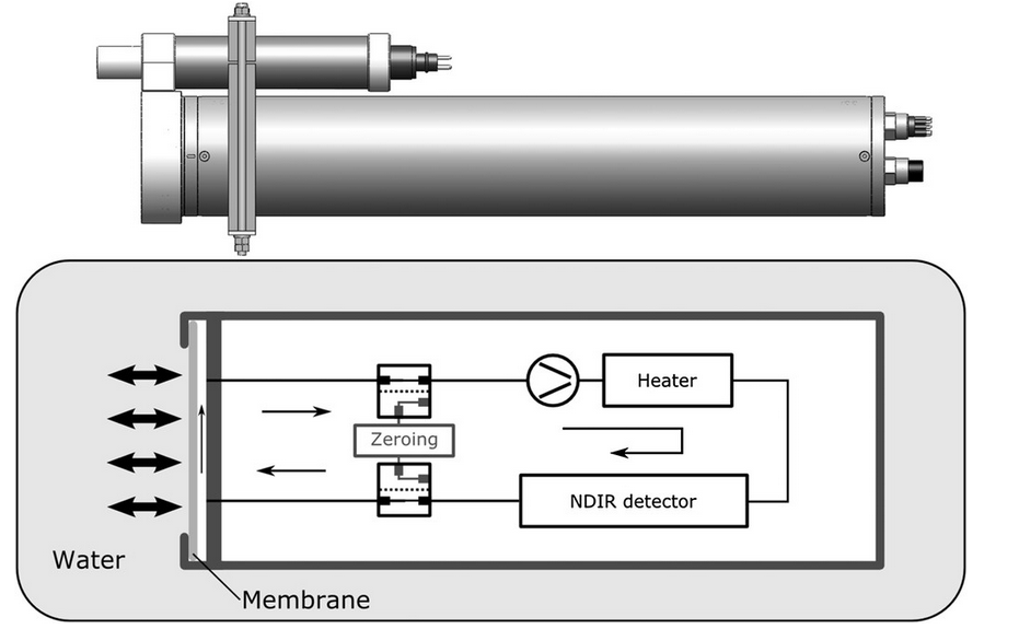
Fig. 3.1 (top) Drawing of the pCO2 sensor as used in the present study, but with original form factor. The sensor is equipped with a water pump (SBE 5T or 5M) and a flow head. (bottom) Schematic drawing of the sensor. Partial pressure equilibration occurs at the planar, semipermeable membrane separating the water from the internal head space of approximately 20 mL. A pump continuously circulates the gas between the membrane equilibrator, a heater, and the NDIR detector. Valves can be toggled to realize a zero gas measurement by guiding the gas stream through a soda lime cartridge instead of through the membrane equilibrator [Fietzek et al., 2014].#
3.1.1.1. Hardware design of the new Seaglider (SG) HydroC CO_2_#
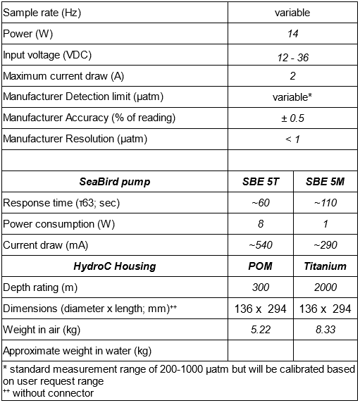
The new SG HydroC CO2 sensor is a modified version of the original CONTROS HydroCTM CO2T sensor to allow for integration inside the Seaglider fairing. The standard high performance HydroC CO2 sensor was changed from ⌀ 89 x 380 mm to ⌀ 136 x 294 mm by rearranging the gas-cycle components and the control unit. This new SG HydroC CO2 sensor is available in a POM housing rated to 300 m for coastal missions and a titanium housing rated to 1000 m for offshore deeper missions. Detailed HydroC SG HydroC CO2 specifications can be found in the specifications table.

Fig. 3.2 CONTROS HydroCTM CO2T Sensor specifications#
3.1.1.2. Membrane type: tough#
[Fietzek et al., 2014] used a CONTROS HydroCTM CO2 with a silicone, polydimethylsiloxane (PDMS) membrane and reported a linear response time dependency on water temperature on the order of -1 s per 1 °C. However, here we use the SG HydroC CO2 sensor with the new robust TOUGH membrane, which uses Teflon AF2400 as the active separation layer and the permeability coefficient is not temperature dependent [Pinnau and Toy, 1996].
3.2. Sensor integration with gliders#
3.2.1. Mounting location#
3.2.1.1. Seaglider#
3.2.1.1.1. SG HydroC CO2#
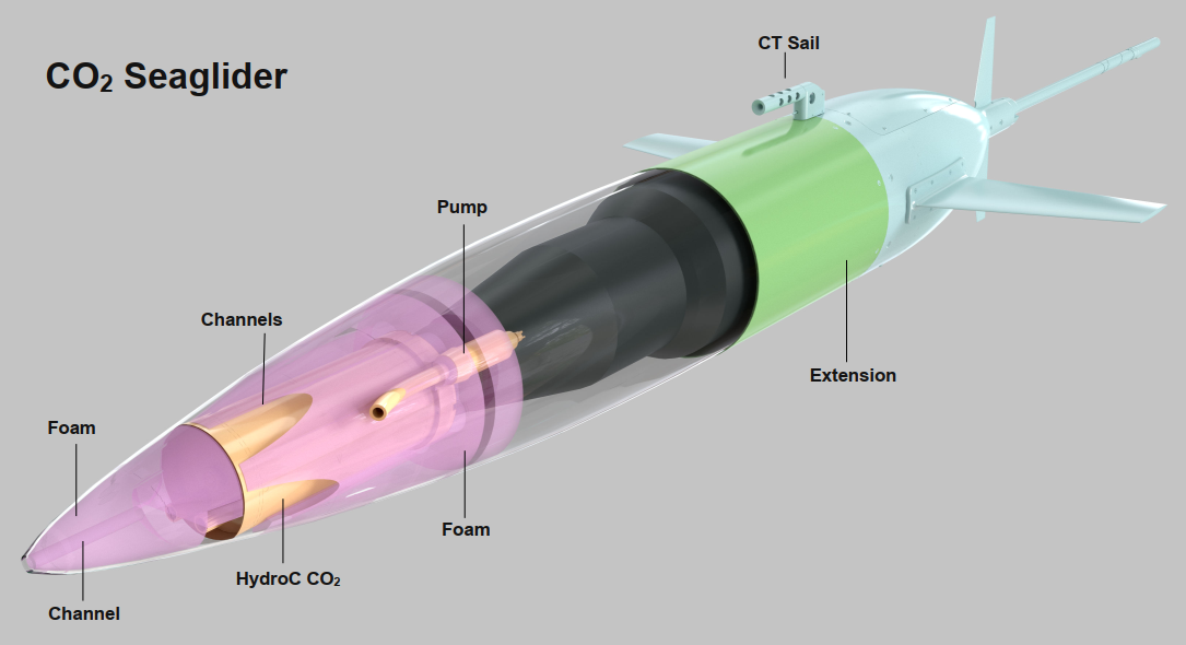
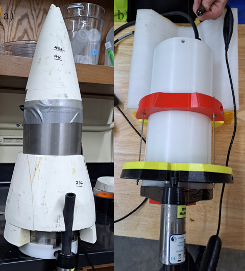
The SG HydroC CO2 sensor is installed in the forward fairing of the M1 Seaglider. The integration requires a 40 cm fairing extension with a fiberglass ring to fit the sensor, Seabird pump, and cables (Fig. 3.3). The STEP file for machining the fairing extension on an M1 Seaglider can be accessed in Section 12.2.3. The sensor must be mounted with the membrane facing aft (toward the altimeter), supporting the escape of potential bubbles within the internal tubing of the sensor during the downcast of the first dive. The 300 m version “SG HydroC CO2 POM” can be installed with simple brackets (Fig. 3.4). The 1000 m version “SG HydroC CO2 Titanium” requires a syntactic foam Engineered Syntactic Systems MZ-22 coat to balance out the weight (Fig. 3.4).
The pump inlet should be oriented such that the pump inlet tube length is minimized, sediment is not entrained if the glider impacts the seafloor (i.e. not on the bottom), it is as symmetrical as possible to lessen any influence on the hydrodynamics and ballasting, and that air entrainment is minimized when the glider is at the surface.
The HydroC CO2 extended cable is passed through between the seaglider pupa and fairings to the aft of the glider.
With the extended fairing closed, it was not possible to switch the seaglider on/off with the magnetic wand. This is resolved when using RevE since the seaglider can be turned on/off from a port in the aft, accessible via the aft hatch.

Fig. 3.3 Schematic view of internal HydroC CO2 integration into an extended M1 Seaglider fairing. Shown is the HydroC CO2 positioned with the membrane facing the transducer for optimal bubble escapement on downcast, Syntactic foam surrounds the titanium housed HydroC CO2 with channels for water flow. The extended HydroC CO2 cable is passed back between the pupa and fairings to the aft of the glider (not shown).#

Fig. 3.4 SG HydroC CO2 sensor mounting designs. a) Titanium SG HydroC CO2 (rated to 1000m) in a custom syntactic foam coat and b) POM SG HydroC CO2 (rated to 300m) with brackets. Figure from [Hauri et al., 2024].#
3.2.2. Battery#
3.2.2.1. Seaglider#
3.2.2.1.1. SG HydroC CO2#
During the initial CO2 Seaglider development, a 10/10/24 V battery setup was used with the M1 Seaglider. The HydroC ran off the 24 V battery because it requires extra voltage during warm-up.
During this project, the max allowed current through the tailboard was 1 amp. When the sensor was on with heating at max and the external pump on it required 21W, which, at 24V, is just under 1 Amp so this worst-case scenario during warm up was OK. Normally the water pump does not have to be on when the heater is on so nominally we expected the power draw of the HydroC to be 14W = 0.6 Amp which was well below the max allowed current of the tailboard.
We estimated 18 days mission longevity given the CSG HydroC CO2 consumes around 7W (@13V) at 5°C water temp including the 5M Seabird pump.
3.2.3. Communication#
3.2.3.1. Seaglider#
3.2.3.1.1. SG HydroC CO2#
The Seaglider firmware has a feature to allow easy integration of “logging devices,” which provides a way to build commands for the pilot on land to switch the sensor on and off and change sampling strategy during the mission (on/off below or above certain depth) when it comes to the surface and communicates with shore via satellite. The HydroC CO2 is used in LogDev mode (logging on sensor, allows the user to add a new sensor without changing the seaglider code base), rather than SerDev mode (serial comms with sensor and data transfer to glider CPU). An ASCII configuration file (hydroc.cnf file, see Section 12.2.1) is used to define the device configuration. For more information see the 4900041 - Logdev User Guide.pdf (provided during training or included with the seaglider documentation).
To take full advantage of the ability of the HydroC, a more-advanced electronic integration was carried out using Smart Interoperable Real-time Maritime Assembly (SIRMA™, registered trademark of Cyprus Subsea Consulting and Services, C.S.C.S., Ltd.). This small programmable electronic circuit contained hardware elements to adapt the sensor power and communication requirements to those available on the host platform. It also allowed for separate storage and processing capabilities to supplement the main host processor that controls the flight, sampling, and telecommunications of the host. SIRMA was also programmed to extract raw data from the HydroC and calculate bin average of some of the output fields which were useful for real-time mission adaptation and confirmation of sensor operation. Three levels of output were allowed, depending on how much surfacing time could be tolerated before continuing the mission (Baud rate for Iridium is very low, on the order of 4800 bps).
The SIRMA was also used to set thresholds and in the event any of the parameters of interest reached a threshold, an error would be logged to the Seaglider log file (see Section 5).
The HydroC sleep mode only allows for wake-up after a set time and there is no way to interrupt with a serial cmd such as ‘wake’. It is however possible to come out of sleep mode when the power to the sensor is cycled. This means that sleep mode is best not used at all and the sensor is simply turned on or off when required instead.
